Monday, 18 July 2011

Back Probing

Back Probe Testing

This blog discusses simple back probing connectors on the bench, I’ll go through all the steps on how to back probe. In practical class we used multi-meters to do a basic back probe, we went through the steps on how to set up and test the meter and I will cover these steps.

1.     Firstly we setup the multi-meter by setting it to Ohms and making sure that the leads weren’t touching making it an open circuit.The we do these steps are to ensure that the multi-meter is working correctly.

2.     The reading on the screen showed 0.L as shown above, this means open circuit because the probe wires are not touching or connected.

3.     Next I touched the two probe leads together and got a reading of 0.2Ω, this shows that the circuit is closed as both probes are touching each other.


Back Probing Connectors
1.     We received a hard shell connector with terminals and wires attached so that we could carry out tests.

2.     Next I back probed a wire by gently inserting a pin into the back of the lead (as shown below) and then probed the front on the other side; I then measured the resistance which was 0.6Ω.


If you get a reading on the multi-meter then the back probe was successful because this shows that there was a good connection made and the circuit is closed. However if you get a 0.L display then the circuit is still open, this means that either of the probes are not connected correctly.

Exhuast Analyzer


Exhaust Gas Analysis
In today’s class we covered exhaust emissions and then in practical used an exhaust analyser to analyse the emissions on our own vehicles. This blog covers the steps we took to carry out testing and our readings, I’ll explain each reading and what the results show.

Firstly we setup the exhaust analyser so that it could calibrate the system, it needs to get a good reading of the oxygen so the analyser probe was not inserted when the machine was calibrating.

*When carrying out tests it is important to do them in an open space to avoid CO poisoning which can be deadly.

The readings we got were:

          CO (Carbon Monoxide) = 0.001
Means: Shows almost no amount of CO which is expected because probe has not been inserted in exhaust, the reason I got the above reading is because there were a couple of cars running so there were traces of CO in the air.

          HC (Misfire):12
Means: There is no detonation or burnt gas in the air so the reading is 12ppm, this reading will change when the analyser probe is inserted.

            CO² (Carbon Dioxide) = 0.00
Means:The reading was 0.00 this is because it was only reading the fresh air so there shouldn’t be any readings unless the car is running in a closed of space for a while.
          O2 (oxygen) = 20.90
Means:O2 is high because it is reading the oxygen in the air so it should be high, this will change when test are carried out on the vehicle.

Start the engine idling cold and then insert the analyser probe into the tailpipe of the vehicle and allow it to analyse the emissions. 

The readings I got at Cold Idle are:

            CO=2.89
Means:The CO is high because the engine is cold so it is running a richer air/fuel mixture.

HC=788ppm
Means:Because the engine is cold there is a richer air/fuel mixture and also there is some misfiring occurring.

CO2=12.6
Means:The CO2 will slowly increase as the engine warms up, this is because the higher the carbon dioxide reading the more efficient the engine is operating.

O2=5.15
Means:Because the car has just been started there is still some O2 in the exhaust system this will decrease as the car warms up.


Next readings are with the engine warmed up.
The readings are:

          CO=0.58
Means:The engine is now warm so the air/fuel mixture is not very rich so there is a lower CO output.

HC=235ppm
Means:The mixture is not rich anymore as the engine is using less fuel, therefore the HC has dropped and there is less misfire.

CO2=14.2
Means:With the engine running a operating temperature the CO2 is slightly increased and more ideal, this is because ideal combustion produces large amounts of CO2 and H2O.

O2=1.10
Means:With a warm engine more of the O2 is being burnt so less O2 is exerted from the chamber.


The next reading is with the engine warm and running at 2500RPM.
The readings are:

          CO= 2.5
Means: because the engine is running at 2500rpm the air fuel is richer because more fuel is being injected into the mixture.

          HC= 434ppm
Means: Air/fuel mixture is very rich because the throttle is open and therefore more fuel is being forced into the chamber.

          CO2= 10
Means: because the engine is running rich the CO2 is lower and this shows that the engine is not operating not efficiently.

O2= 1.3
Means: the air/fuel mixture is burning smoothly so O2 remains low; this shows that isn’t much misfiring occurring.

Basically the readings vary on the condition that the engine is under; if the car is cruising then it will run efficiently so CO2 and HC will be low. And when the car is speeding or under load then the air/fuel mixture will be rich, so the CO and HC will be high indicating that the car isn’t running efficiently.

Glow Plug Testing


Testing Glow Plugs
In today’s practical class we were shown a demonstration on testing glow plugs, this blog covers simple procedures on testing glow plugs for damage and if they need replacing.


A glow plug is a heating device used to ignite diesel engines.Diesel engines, unlike petrol engines, do not use spark plugs to induce combustion. Diesel engines rely solely on compression to raise the temperature of the air to a point where the diesel will combust spontaneously when introduced to the hot high pressure air.


Testing
With an ammeter:
Connect the ammeter in series with a glow plug and activate the relay, the current will spike to about 40 Amps and slowly decrease to about 15 Amps over a 3 to 5 second period.
If it's shorted the current will just go to 40 Amps and stay there because since the current is not flowing through the element heat build-up doesn't occur and current doesn't decay.
*We do not check for resistance when testing glow plugs because a faulty glow plug can still pass the resistance test.


With a power source:
We used a simple car battery and connected the positive lead to the thread of the glow plug and the ground cable to the terminal of the glow plug.
The element at the end should heat up from the top of the plug down to the centre, if it heats up from the middle or bottom then the glow plug possibly needs to be replaced. The image below shows the setup and heating of the test.


Common rail diesel engines


Diesel Common Rail engines

A common rail diesel engine is quite similar to a normal diesel engine; the only real difference from a normal diesel engine is the fuel injection system. The common rail direct injection system uses electronic circuits to control how much fuel is being injectected into the cylinders.

Also the Injection timing, Start of injection, Injection quantity and the injection pressure are all accurately controlled with electronic control unit.A high pressure pumpdriven by the engine shaft, is used to pump in very high pressure fuel from the tank and into the common rail.

A common rail is basically a hollow shaft by which the fuel is delivered and maintained at a very high pressure (which is about 2000 bar). During the firing sequence of that particular cylinder, the high pressure electronically operated injector will be opened and fuel with a pressure of 2000 bar is injected directly in to the cylinder.

This high pressure fuel will be atomised completely and leads to complete combustion of the fuel, thus avoiding bad emission.


Sensors In Relation to the ECU


ECU in Relation with Sensors

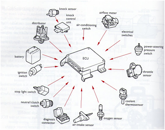
Controlling the engine is the most processor-intensive job on your car, and the engine control unit (ECU) is considered the most powerful computer on most cars today. The ECU uses closed-loop control; this particular control scheme monitors outputs of a system to control the inputs to a system (controlling sensors), managing the emissions and fuel economy of the engine.
By collecting data from all the different sensors in the engine, the ECU knows everything from the coolant temperature to the amount of oxygen in the exhaust. With the data it collects from the sensors, it performs millions of calculations each second, including looking up values in tables, calculating the results of long equations to decide on the best spark timing and determining how long the fuel injector is open. The ECU does all of this to ensure the lowest emissions and best mileage. 

ECU receives input from these Sensors


It then sends commands to these components